No comments
Eastern State Penitentiary Construction Sequence
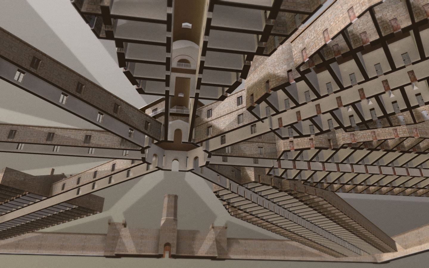
This time-lapse animation with audio narration uses the tools of virtual reality to reconstruct the appearance of Eastern State Penitentiary during each year of its 148 years of operation from 1823 to 1971. This reconstruction is based on original plans and primary sources about the jail’s architecture. It uses film to reveal how the building’s envelope was expanded and modified each decade in response to evolving design philosophies, public attitudes towards incarceration, and the ever-expanding size of today’s carceral state. VIEW PUBLICATION >